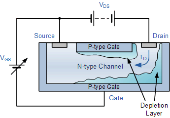
When the Large negative bias is applied: When the large negative gate to source voltage is applied, then this large negative electric field will contribute to increment of the width of the depletion region.Besides, the current flowing from drain to source flows from the region of high resistance to low resistance, thus the voltage drop will be created.

This is because the gate is more negative at the points which are nearer to drain than to source. The width of the depletion region is more near the drain terminal and less near the source terminal.

This is because as the width of the depletion layer increases the space provided for electrons to flow from source to drain will decrease and eventually the drain current decreases. The wedge shape depletion layer so formed will reduce the magnitude of the current through the N-channel. Due to this the width of the depletion region is more in N-Channel than in P-channel. The N-channel is moderately doped while P-channel is highly doped.

Simultaneously, the positive voltage is applied to the drain to the source terminal. when the gate to source voltage is negative, then the width of depletion region starts increasing.

The two PN junctions are form by the N region and the space between that is P region is called a channel. The JFET in which the current conduction takes place only due to holes as majority charge carriers is known as P channel JFET. Its construction is similar to the N channel JFET excepts that it consist of a P type silicon bar with two N type heavily doped regions diffused on opposites sides of its middle part. The construction diagram of P channel junction field effect transistor (JFET) is shown in above figure.


 0 kommentar(er)
